Frequently Asked Questions
System Setup
In CMD window, ping the corresponding MCU address, below screenshot shows the communication of PC and specific MCU is good.
If this communication is good, the issue is located at Mitspro level.
If this communication here is bad(no reply), the issue is located at PC or cable connection level.
(1) Mitspro Level checking:
Check ArbinSys.cfg, and make sure the MCU has the correct IP address specified.
(2) PC level checking:
Check PC’s TCP/IP setting, normally Arbin PC is set to a fixed IP address: 196.168.1.100.
(3) Connection level checking:
Check the Ethernet cable connection of the PC and Arbin Cycler, if there is an ethernet switch, make sure the green light is on or flashing at the occupied ethernet port.
Note: Some system has an ethernet switch located on the aux chassis, check the following:
- Aux chassis’ power button is on
- Power cable is connected
- Ethernet cables are connected to ethernet ports instead of CAN ports.
Schedule
It is a preset Unreasonable Voltage Check setting in Schedule Global page, it is by default set to 20% of max voltage of test object file. This safety is usually used for detecting loose connection of load or abnormal low voltage of battery. If your test intends to handle the lower voltage, simply lower the percentage or delete this safety limit.
CCCV is the standard Constant Current to Constant Voltage control, while CCCV_WRM inserts a very short ‘relax’ period between CC period and CV period. During relax time, system current output drops to almost 0, and the corresponding load voltage drop will be measured by the system. Then an Internal Resistance value is calculated by IR = voltage drop / Current drop. This IR value is used for CV stage voltage control (current based PID control).
Advantage of CCCV_WRM: It provides the latest IR value for best Voltage control, it also eliminates the need of adding an IR step before voltage control.
The disadvantage of CCCV_WRM: There is an extra current drop in relax period which does not exist in standard CCCV. Also, the IR value calculated may be less accurate if the CC value is too small to create an effective voltage drop.
Currently, there is no way to realize this synchronization by IV system only. But we can use DI/DO module to realize it.
This unsafe is caused by Step Control Error Check setting on the Schedule global page. It will monitor the actual current/Voltage/Power output value and compare it with the schedule setting value, unsafe will happen when the discrepancy between the setting value and the actual value is larger than the setting limit. They are designed to detect open circuits or short circuits caused by loose IV cable connections, it also detects abnormal output when the system has problem.
Test Setting and Batch/Mapping file share the same Auxiliary Channel Virtual Index.
There are many reasons for schedule stopping, here is a checklist of possible reasons:
- Load voltage outside of safety limit.
- Load voltage lower than Unreasonable Behavior Check voltage.
- EIS function enabled but EIS device not correctly connected.
- UPS function is enabled but UPS does not correctly connect.
Most voltage control requires an Internal Resistance (IR) value of your load. This value can be obtained by an Internal Resistance control step. If you encounter bad voltage control, try adding an IR step before the voltage control step.
First Check sdu writing issue:
- Check sdu’s clamp setting, does the clamp limit current output?
- Check step’s Max Current setting, does Max Current smaller than setting current and indicates a smaller current range?
Then Check the Hardware issue:
- If the current is almost zero, check Switching Power Supply’s air switch, is it turned on?
- If charger/discharge current is less than the setting value:
- Check power V++ and V--, possibly Power supply module issue.
- In the manual calibration window, check multiple current points, if the output current value is always a certain portion of the set current value, it indicates there are some small current loops broken.
- Check the current output in different current range, more information could be get with Circuit diagram.(fuse burned, Main current loop broken, etc)
- If charge current only drops when the voltage is high(For LBT21), it indicates V++ is too low, check V++.
This error indicates too much data logged at a very short period of time. Check the schedule, make sure the data log setting is appropriate.
This error indicates an IR(Internal Resistance) step can not get a valid result value. Typically because the Setting Current(Amp) is too small or the Time Period is too short. Try to increase the setting current and Time period(>50ms).
This error indicates Aux channel lost communication with IV channels. It usually happens when the Batch/Mapping file was created/modified without downloading to cycler. It could be solved by downloading Batch/Mapping file:
This checking will only be performed when Channel Based Voltage Clamp option is not checked in ArbinAdvSys.cfg, which means all IV channels on the same IV channel board share a single voltage clamp/voltage check. Then Mitspro needs to ensure all schedules in the same IV board channels have the same Voltage Clamp setting, if not, this “Conflict Clamp V” will pop up.
Recently, almost no Arbin system has shared Voltage clamp, so most of the time, this unsafe is due to wrong Advanced feature setting. Simply check Channel Based Voltage Clamp in ArbinAdvSys.cfg would solve the issue.
Monitor & Control Window
In Control & Monitor window, click the top menu Settings -> Monitor Settings…, then choose the General tab in the pop-up window, you can change the sound file or enable/disable sound under different circumstances.
You need to assign a schedule to this channel, and this schedule needs to have a corresponding auxiliary channel configured(added).
Aux Module
MTCI module is used to communicate with different chamber controllers, troubleshooting procedures are below:
If Monitor&Control Window shows MTCI channel reading 0.00 degree, it means Mitspro setting issue:
(1) Check ArbinSys.cfg, make sure MTCI is configured there, and the Auxiliary page has MTCI channel row’s Controllable checked.
(2) Map/Batch file has MTCI channel correctly mapped to IV channel.
(3) Iv channel already has a sdu assigned, and this sdu has added enough temperature channels inside.
If Monitor&Control Window shoes MTCI channel reading 22 degree, it means Mitspro setting is ok, MTCI board or chamber controller issue:
(1) Check MTCI board setting using ListenForNet, make sure MTCI’s controller type matches chamber’s controller type, and other parameters are matched.
(2) Check the Chamber controller’s setting, and make sure the baudrate, parity, and other parameters match MTCI setting.
(3) Check serial cable, some controller requires crossover wire, but some others do not.
(4) Use Serial Port simulator/monitor software to communicate with MTCI or Chamber Controller directly.
You need to assign a schedule to this channel, and this schedule needs to have a corresponding auxiliary channel configured(added).
Result Data
This is a common issue at Microsoft Access, you can open this .res file in Microsoft ACCESS, then click File-> Compact&Repair Database to shrink this file. This action can only be done when a related test is not running.
This issue roots from the Windows system, which adds a comma to >1000 number automatically. We can fix it by changing a regional setting:
Files extension is hidden in Windows by default. You can unhide it by:
- Open Control Panel > Appearance and Personalization.
- Click on Folder Options or File Explorer Option.
- Click the View tab, under Advanced Settings, you will see the option Hide extensions for known file types. Uncheck this option and click on Apply and OK.
Windows 10 users may also search for File Explorer Options in the Start search box and open this box.
For more details, refer to https://www.thewindowsclub.com/show-file-extensions-in-windows
Usually, it’s related to MitsDB.dll registration. Try the following steps:
- Make sure these three files are in the Mitspro location:
- Search “cmd” at bottom left window then open Command App and “Run as administrator”.
- Input “cd C:ArbinSoftwareMITS_PRO”, press ENTER.
- Then input “C:WindowsMicrosoft.NETFrameworkv4.0.30319RegAsm C:ArbinSoftwareMITS_PROMits_DB_Ent.dll”, press ENTER
You should see something similar to:
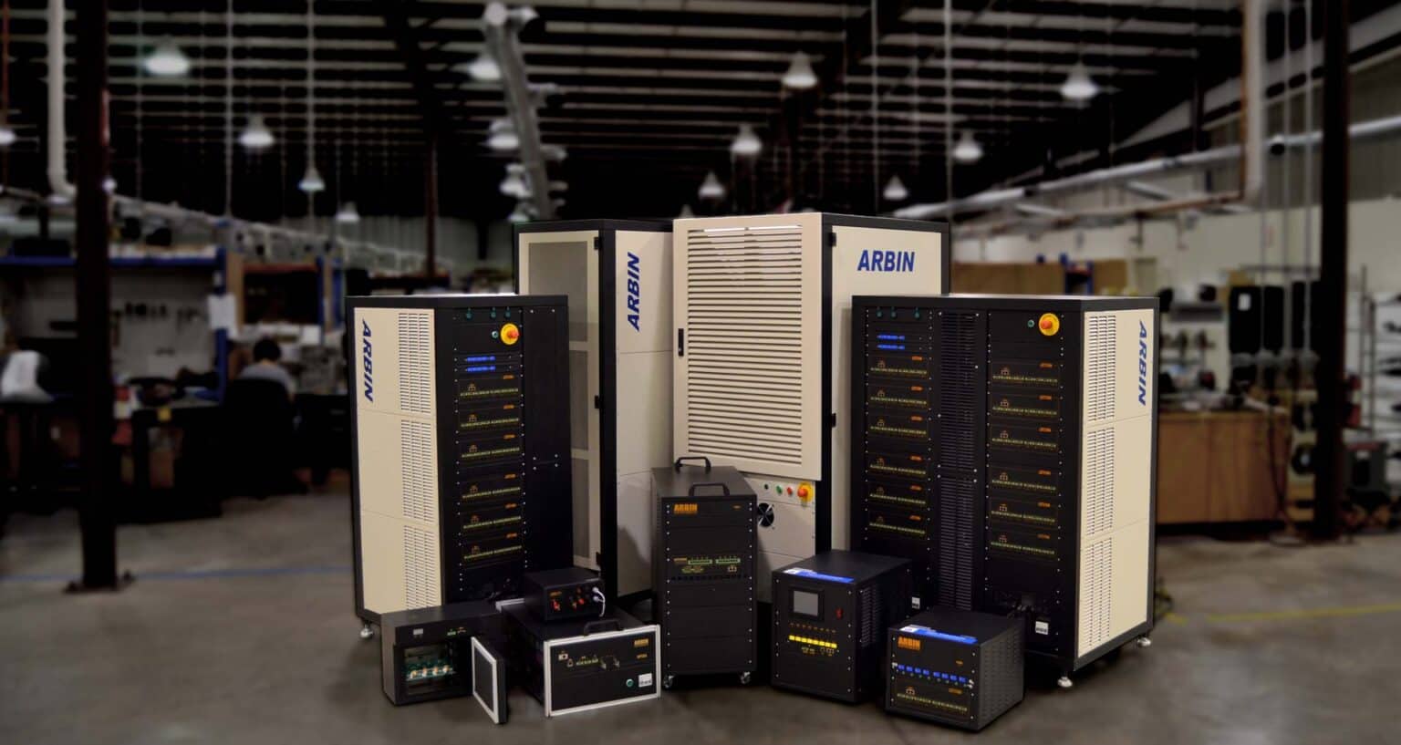
Ready to Build Your Arbin Battery Testing System?
Our expert team is ready to help you build a complete testing system that meets your specifications. Fill out the form linked below to request a quote and start the process.